
Instrumentation firm VEGA Controls looks at performance issues that can arise with an aspect of automation that is a popular fixture in the water industry
Gravity thickener machines are widely installed and used in wastewater treatment plants, water treatment plants as well as in a wide range of industries with waste or solids separation requirements. These include: food and dairy, pulp and paper, abattoirs and special aggregates industries.
The machines are primarily used for water-volume reduction prior to processes like digestion, dewatering/ drying, and transportation for incineration or disposal. They are continuously operating machines which thicken sludge by gravity using a revolving porous filter belt or conveyor. And they generally produce a still pumpable, but much thickened sludge.
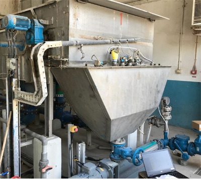
A typical gravity belt thickener out-feed. Level controls over the outfeed hopper regulate the pump speed and operation, and the feed into the gravity belt thickener.
They employ the natural tendency of higher-density solids to settle out-of-liquid, employing some additional mechanical assistance to this process of concentration. Think of the example in a kitchen of passing a stock through a sieve, using a spoon to stir and agitate the process to encourage more liquid to pass over a wider area and over cleaner parts of the sieve.
The technique is used in the same way in both industrial and municipal settings. A gravity belt thickener employs ‘gravity drainage’ whereby dilute sludge (typically 0.5% to 1.0%) is introduced at the feed-end of a horizontal filter belt. As the slurry makes its way down the moving belt, any free water drains through the porous belt. The solids are continuously turned, encouraging the drainage of more water through a filter belt to thicken. A drum thickener works on a similar principle of conveying treated sludge (aka flocculated sludge) through a slowly rotating drum filter. The sludge remains in the drum, while the water phase passes out through the filter.
Some ‘dynamic’ systems also employ a partial vacuum or pressure to assist with the filtering to accelerate or optimise the process. There are also presses and centrifuges which carry out similar tasks, all with similar process challenges and using varying control techniques. In most cases, the final sludge is discharged into an outlet hopper as a pumpable, thickened sludge.
The sludge to be thickened may be polymer-conditioned prior to digestion. Or it could be prepared for a further process of mechanical dewatering in a press or centrifuge. Or it might be water-reduced before it is transported to a sludge disposal site or an area of land where it is to be applied as a fertilizer.
Controlling the thickening process
Control of these mechanised processes is key to producing a consistent throughput and output; too fast and the filter systems can be overwhelmed; too little tends to waste energy and capacity, and can have a detrimental effect on the quality of the final sludge.
To do this, the machines employ a variety of level and pressure sensors – among other devices – to support control of the process and provide feedback on how it is running. For example, in-line pressure sensors and pumps, differential pressure sensors on filters or across pumps, level in-feed sensors on receiving hoppers (and even on the belts themselves), and sensors to measure the density of incoming and outgoing media.
All of these measurements help the machine manufacturers, and in turn the plant operators, optimise performance and control of the process. Really good automated control equals less power consumption, and a better quality output – every gram of water extracted means less energy in transport, further processing or drying. When that gets scaled up to a large wastewater network, or large-scale industrial process in food, paper, steel or aggregates, these grams of water can quickly turn into significant savings across a fleet of machines and sites.
The issues that come up when attempting to secure reliable control are manifold. If we look at the instrumentation that provides the data, accurate measurements provide benefits that are once again amplified through the cost and processing chain of this continuous, automated process.
Challenges of pressure control
One critical element is the pressure sensors used to monitor performance in delivery systems, pumps, recirculation or outfeed circuits. Pressure monitoring sensors have to be sensitive (and must be kept away from direct contact with the arduous process conditions). Yet ideally they need to be flush-mounted in pipelines and vessels to avoid blockages in the sludge they are monitoring.
Both types of constraint can lead to errors. For example, recessed protected sensors become prone to blockages or air pockets. These can be worked around with air or water flushing, but this adds cost and complexity and maybe unwanted water into the process. On the other hand, by flush mounting them, you expose the sensitive, thin-metal pressure diaphragms which can be prone to abrasion damage from particles in sludge. The result? Drift in the accuracy of readings, which, when trying to extract every gram of water or solids, can negate all that optimisation work.
So care needs to be taken in the mounting and positioning of pressure sensors. Air pockets and blockages in small recesses can play havoc with readings, and, in turn, necessitate extra servicing, recalibration and repair, which can introduce costly downtime and interruptions. Unfortunately, the outcome can be overflowing or over-running machines, often attributed to a lack of accurate, proper control. Machines are often switched to “run in manual” mode, to counter this. However, there is another solution when it comes to making these pressure measurements.
Flush mounting without fear?
The problems of blocking, flushing, cleaning, wear and damage can all be avoided with something as simple as using ceramic pressure sensors that can be fully flush-mounted. A concealed elastomer O-ring can reduce exposure to wear.
This ceramic diaphragm technology is already proven in slurry pipes in both the mining and recycled paper industries, with their respective bombardment of equipment with either sand/grit or ‘paperclips’ – all fatal to metal diaphragm devices. “Flush mounting without fear” using ceramic pressure transmitters also means no mis-reads as a result of blockages or air pockets due to syphon/vacuum effects from flows across recessed pipes or fittings. Another benefit of ceramic cells is a vastly improved resistance to pressure-shock overload and ‘water hammer’, once again providing better long-term accuracy and stability.
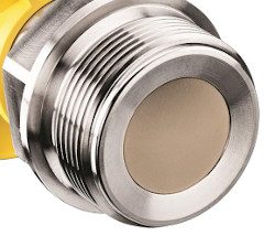
Ceramic flush pressure sensors provide hard wearing diaphragms to avoid blockages and provide accurate pressure monitoring.
Some ‘dynamic’ thickener systems, using pressure or vacuum, also require a differential pressure measurement across the filters or pumping systems to detect any drop in performance. This information is invaluable, as again it can be used to directly control speeds of filter mesh or flow rate, to avoid overflows and flooding. This can also be achieved with the use of two ceramic-faced sensors, in a remote electronic differential pressure configuration, which again provides a direct flush-mounted measurement.
Measuring density
Density is another parameter monitored during processing, normally via in-line density sensors. Again, they are vulnerable to build-up and wear. An alternative or back-up option is a flush-mounted or top-mounted ceramic-cell differential pressure system, which can be used to provide a continuous density measurement in vessels at certain process points. These often simple and innovative pressure-measurement solutions can be employed to maintain the correct feed rates and quality of output, and to help maintain process reliability.
Keeping level control
When it comes to level controls in sludge handling and feed applications, conductivity-based point-level switches and ultrasonic level sensors are the incumbent technologies, and a familiar fixture in the water industry. These sensors are often required to work within a confined operational space with a close proximity to splashing, sticky sludge. This presents challenges for ultrasonic sensors such as echo loss or ‘blocking distances or dead zones’ in the near-range. Similarly, conductivity-based point level switch probes encounter locked-up switch signals.
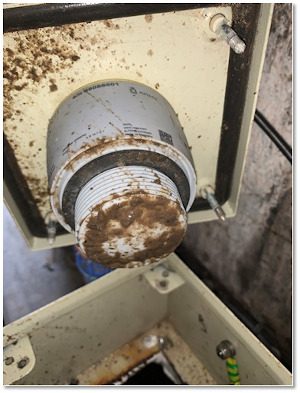
The result can be machine reliability issues, nearly always caused by build-up and sensor fouling, which can lead to automated processes malfunctioning. A residue build-up on a conductivity probe will often lead to a device remaining in a switched state until someone is called out to site and the probes are cleaned.
Maintenance call-outs for this kind of ‘nuisance false high level’ are costly and a strain on maintenance teams. The machines can often overflow or flood, resulting in production down-time, in addition to time-consuming, unpleasant clean-ups, and even damage to equipment. When sensors are working at the limits of their capabilities, there are often unsuccessful attempted ‘work-arounds’ and the upshot is a loss of confidence in automated control systems. The thickeners are run in manual or semi-manual mode, and what should be virtually continuous and automated, becomes a batch-operation with personnel devoting time to supervising the thickeners, where they could be spending it elsewhere on plant.
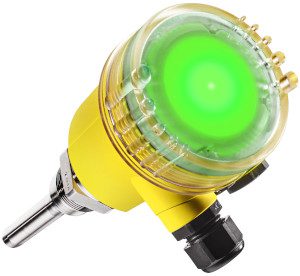
Radar-based sensors overcome many of these issues in level monitoring and control. They can work in more confined spaces, without ‘dead zone’ or ‘blocking distance’, and can operate comfortably with build-up and water deposits on the sensor face – with no loss in the accuracy of readings and the reliability of control.
In conjunction with a controller they can also be used for ‘non-contact, point-level control’, to replace probes. Until now, they were perceived as expensive, but new compact 80-GHz devices are both highly affordable and competitive with ultrasonic and even point-level switches.
Extra benefits like Bluetooth (for remote adjustment and transfer of operational information), means they can be monitored in real-time, from a safe position, to ensure they are delivering the performance needed.
If a separate, discrete back-up point-level device is needed, another alternative is an admittance-based level-probe solution. This adds expense compared to a conductivity switch, but can deliver much better reliability with its self-adjusting technology that avoids the ill effects of residue build-up.
Every application is different, but many of the challenges are similar. Whether you are a machine- or system-supplier, or an end user with existing equipment, you might want to consult with a good level and pressure supplier. Be prepared to collaborate and innovate with them, and even to do some trials and tests at problem sites. You could be surprised at the cost effective improvements to yield, quality and efficiency.